Quick Summary
If you’re just here to use the ornament builder, here it is and here is a tutorial. Sorry mobile users, the actual editor is desktop-only, you can just see the dangling simulation. If you make something cool, please let me know on X.
In this article I describe how I tried to make an ornament by hand, but found that despite multiple attempts the pieces never quite hung right when they were linked together. Fortunately I overcame my lack of intuition for ornament physics by using the power of simulation to create a perfect-to-design result. And, now that it’s a program, these results are quick and repeatable!
Here is the before and after — note the uneven spacing between the pieces on the left versus the right.


The Story
Every year my family exchanges handmaid gifts. Last year was boxes. This year we planned a simpler project: a family tree ornament made of laser-cut walnut pieces connected by jewelry jump rings. It did seem simple at first: the initial attempt only took a short time: I sketched some pieces, connected them with hoops, and… the result was meh as you can see in the before image above. Uneven gaps, pieces touching, and the whole thing hung askew.

I tried three times with this manual approach and this is my best attempt. And, not only was I unhappy with the look of this droopy tree, due to (Harkonnen-esk?) family dynamics I was instructed to rearrange a few names, which of course would screw up the hanging again.
I really wanted the pieces to hang evenly and I didn’t want them to touch. If the tensegrity table can exist, then this had to be possible. But I would need help — instead of just YOLOing it freehand like before, I decided to write a program to simulate exactly how the pieces would hang to ensure a perfect end result.
The Plan
The laser cutter takes an SVG file as input, so that needed to be the output of the program. I decided the program would consist of:
- An editor to define the overall shape and pieces and how they were connected.
- A simulation engine to show how the pieces would hang.
- A preview of the output SVG.
The Editor
I wanted even spacing between pieces and after my misadventures with the manual approach I didn’t want to try drawing the pieces by hand again. So I thought the editor should allow placement of the names, then automatically generate the pieces around them. The first thing that came to mind for this was the cells in a Voronoi Diagram. I researched how to construct a Voronoi from a line, not a point (to better cover the text), and although it sounds like there’s something called a segment Voronoi diagram, I ended up just taking the easy approach of including lots of points along the line of a name, then merging those cells together.
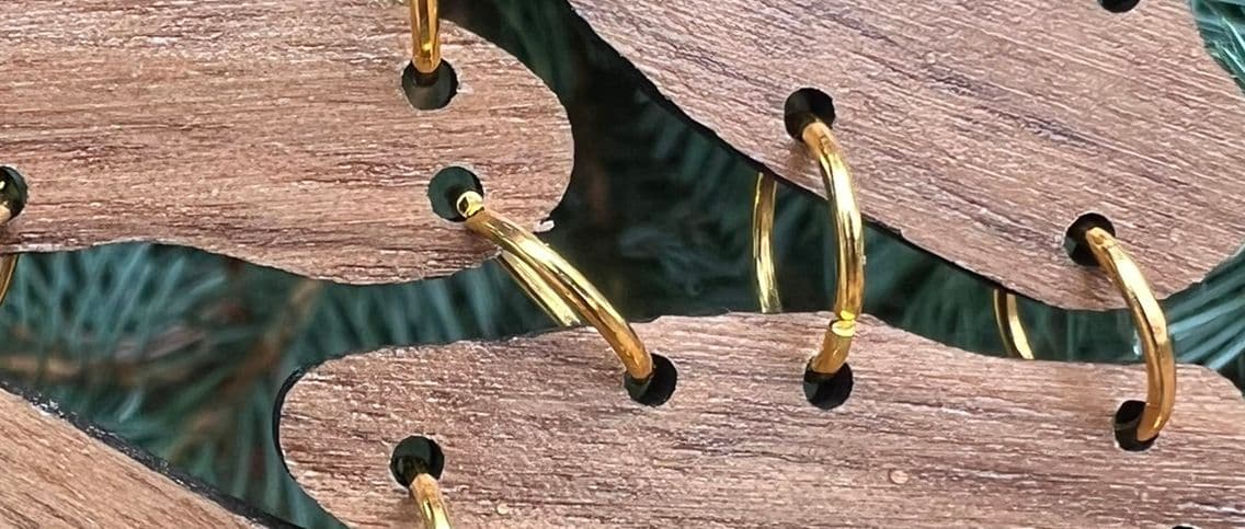
An early version of the program made this visible, so for example for a segment input like this:
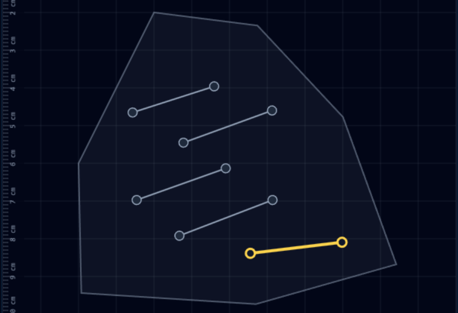
The Voronoi cells after computing the diagram and merging cells from the same line looked like this:
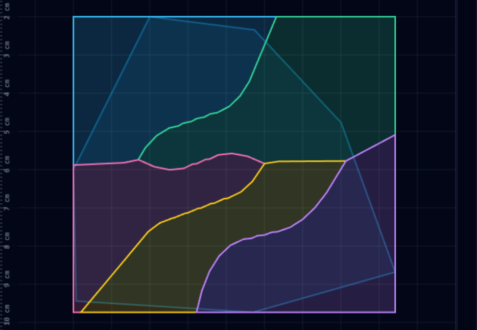
After computing the Voronoi diagram I needed to somehow put gaps between the cells. I decided to start by drawing the edges of the cells, compute a distance field from those edges, then apply a distance threshold so that the edges would be thickened up to N pixels from the center.
I’ve used this trick before and I like using it in two steps: first expand the edges as above, but farther than you need. Then, compute a distance field in the other direction, from the remaining cell out into the edge, and “grow” the cell. This gives a nice rounded effect.
A distance field is also a great opportunity to apply noise, so I added a few optional layers of open-simplex.
Here’s the result of that process for the above:

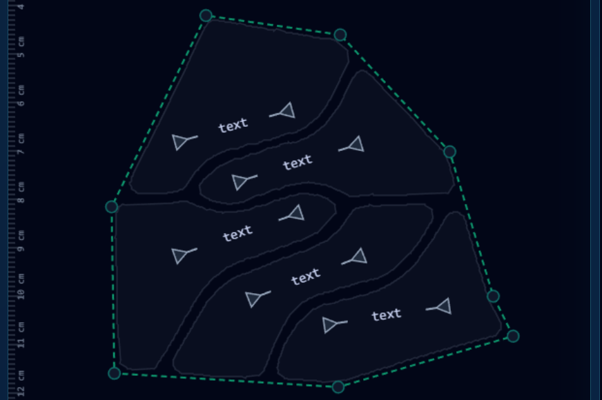
Finally, the simulation was going to need polygons, not bitmaps, so I had to trace them from the distance image. In the final editor version, the traced polygons resulting from these steps are just rendered behind the editor itself.
In addition to the shape outline and pieces, I also added support to the editor for placing connectors, at which point I could move on to the simulation.

The Simulation And Results
Modern development is an embarrassment of riches and it didn’t take long to find matter-js which seems to cover things way beyond what I needed it for. After some finagling to get concave shapes working by loading poly-decomp it seemed ready to go. This part was actually incredibly plug-and-play. With my polygons, I just wired the connectors up as constraints and let it run.
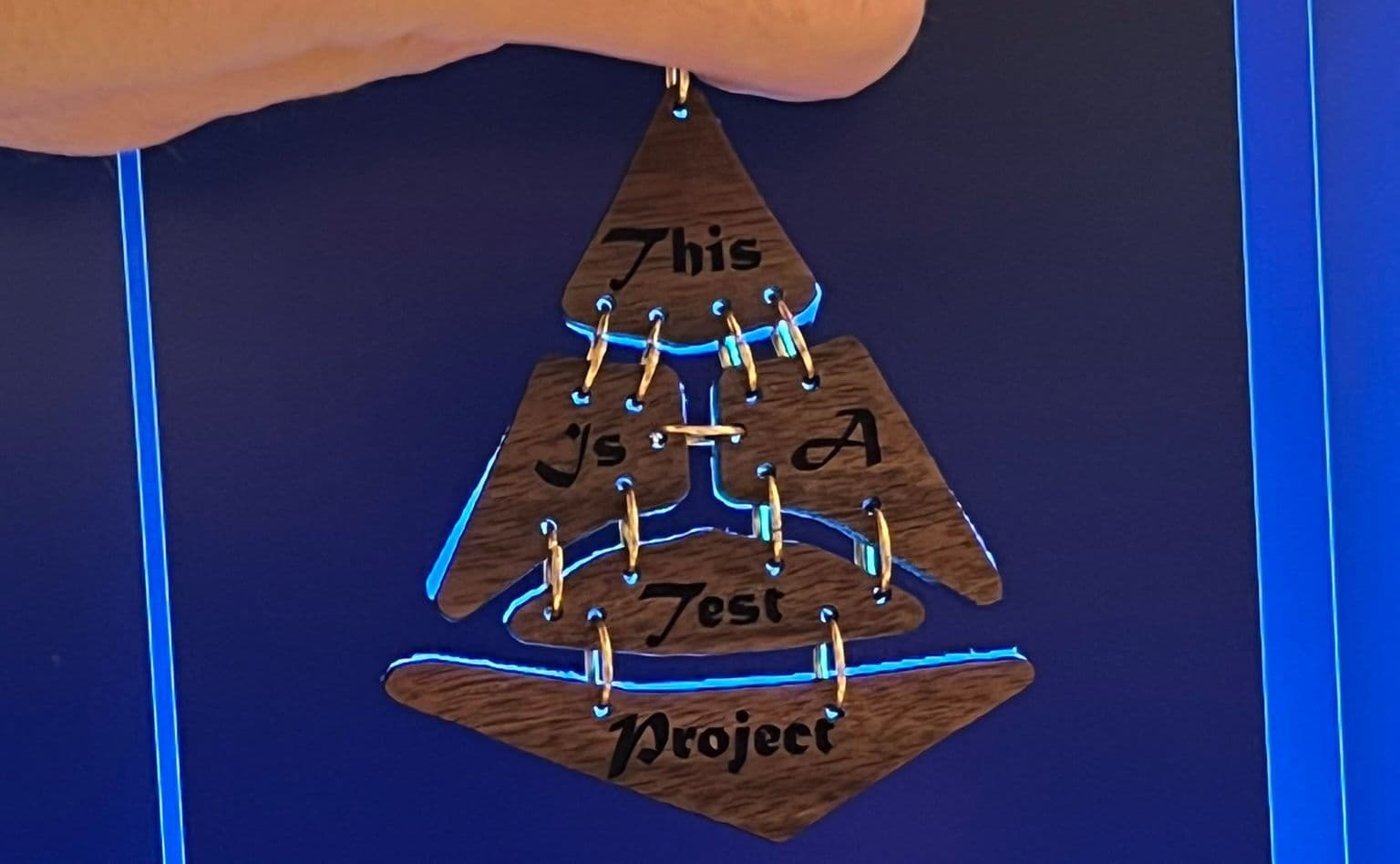
I created a simple test project, used the simulation to guide my connector placement, and ended up with a nice-looking result. It was time to cut the pieces!
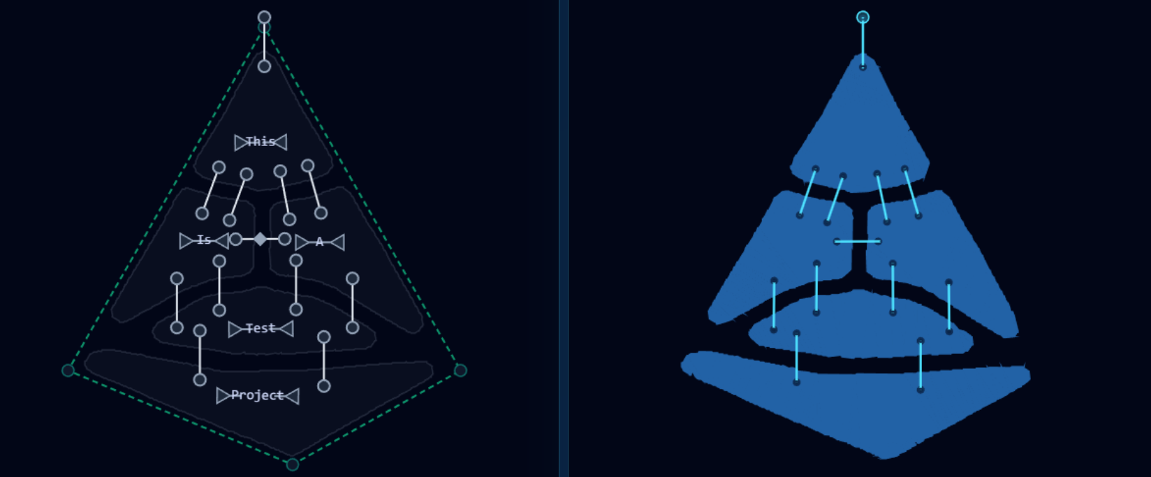
Disaster
I cut the pieces, used pliers to assemble them together with jump rings, and observed… disaster:

So what went wrong? Why was the simulation not accurate?
The problem was that I had modeled the connections between pieces as rigid constraints, but in reality the jump rings themselves were rigid, but pass through holes in the pieces and are somewhat loose in the hole. This meant that their effective length was different depending on whether the pieces were pulled apart (tension), or pushed together (compression). So in this test project, the jump ring in the center is under compression, and it slopped around enough in the holes to let the pieces touch.
The Fix
As a solution I decided to model the connections as a three-link chain: at each end of the main link there would be two tiny links allowing the connection to “slide around” in the hole. The holes are about 2 mm and the jump ring 1 mm in diameter, so it could move up to 1 mm in the hole. From both sides this means the connection could effectively change length by up to 2mm.
Once I added the three-link connections to the simulation it was able to “discover” the disaster above, producing pretty much the same outcome. A good step, but I still needed a way to fix it.
To handle compression, I added a “mode” to the connectors. By default they would be set up to be under tension. In compression mode, the holes would be slightly positioned to compensate for the different effective length and keep the pieces the intended distance apart.
Determining which connectors are under tension and which are compression is not always intuitive. It’s a quick iterative process with the simulator, but it reinforces why I had a hard time with the manual approach.
Once adjusted, the real-life result matched the simulation perfectly:
The Team
This being a front end, greenfield, standalone project, with easily verifiable results, in 2025, it would be madness to not use AI assistance. I started out by writing a prompt for Claude then decided to ask Gemini to write a project plan. The project plan was helpful because I was able to ask Gemini CLI or Claude CLI to “implement phase X” then I could test it out/review it after each step. I started out alternating between Gemini and Claude, then found Gemini was doing just fine so I stuck with Gemini since I wanted to get more experience with it.
This is a pretty complex application, and with the help of AI I did it basically in a couple of partial weekends and evenings, including a few rounds with the laser. I’d say that although I was pretty specific in what I wanted in my prompting, probably 95% of this entire project is straight from Gemini. The parts it struggled with the most were putting CPU-intensive functions into a background worker and getting the three-link matter-js simulation correct. Otherwise the use of these tools turned something that would have absorbed weeks of my time into a casual effort. These AI tools are definitely making me consider crazier projects within the realm of possibility!
Conclusion
Please try it yourself, leave a star on GitHub, and if you make anything nice, let me know on X. Thanks for reading!